![]()
|
|
|
|
MONITOR!
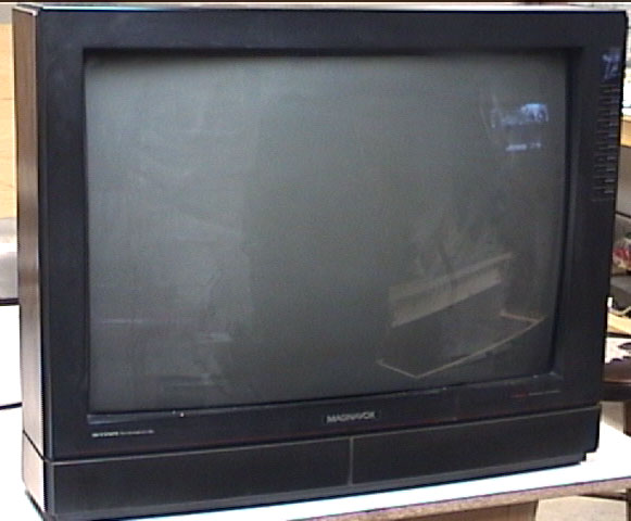
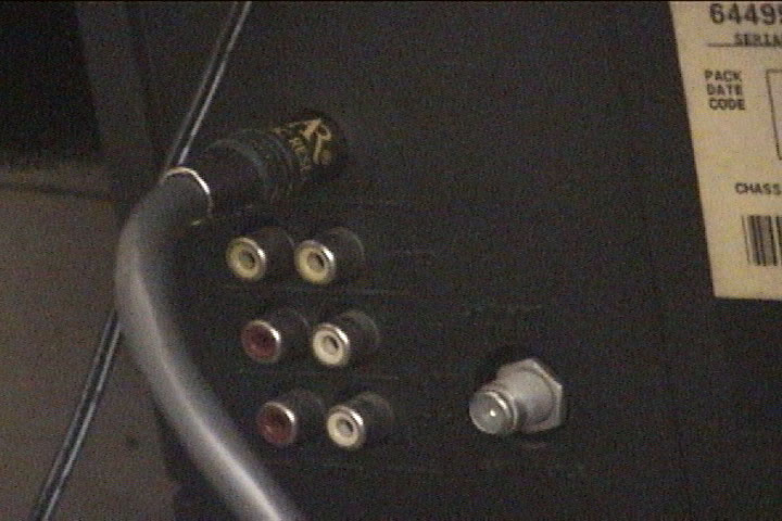
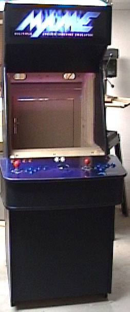
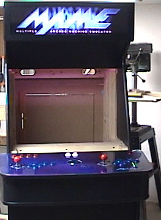
The case being that I made my cabinet from scratch also led to the fact that I could use any type of monitor that I wanted. In my situation cost was an important factor as well as availability. So, with those things in mind I opted for a TV and S-Video. I did a lot of reading on the forums about what type of monitor to use, a "true" Arcade monitor or the other option S-Video. I only considered those 2 options as my most viable. The other option being composite and I am sure there are others. There were a lot of different opinions on which to use, let me tell you that S-video is a viable solution... It was a perfect solution. Given that I was watching a 27" TV with an S-Video input in my office it was a perfect candidate. So, there went the Magnavox... Hello Arcade... Welcome, to your new home...
I
was concerned about realism using a TV. I was left with one un-answered
question:
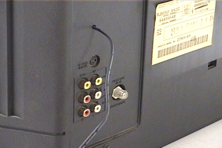
I'm not sure how it works on an Arcade but that's what I was building so I had to come up with some type of solution... As with all necessity an Invention was BORN! The REMOTE Turn/ON Well I'm sure it's not that big of a deal but I patted myself on the back for the implementation of the idea. Here is the scoop.... I removed the rear case of the TV so that I could access the front control panel. At first I was planning on removing the tube and what not but I became intimidated by how large the tube was and whether I wanted to fool with discharging the fly-back ( I think that's what it's called). Anyway with access to the front control panel it had a series of mini-pushbuttons and one was for the ON/OFF switch.
I essentially soldered a wire to this switch drilled a small hole in the back of the cabinet and ran the wire out the back. Now when I touch the wire together it turns the TV ON and OFF.
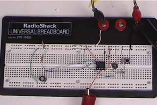
The REMOTE Turn/ON: So, to make things more complicated than they already were I planned on using a 12volt relay to turn ON/OFF the cabinet. The problem was that the relay didn't work in all circumstances, when I hit the power switch to the cabinet the main relay on the power strip (in the How To section) would energize as well as the relay for the TV, great. The problem was the TV relay triggered to soon and thus the TV would not turn ON, bad. So, I needed some type of delay to activate the relay. Born is the idea for the Remote Turn/ON! It's a simple concept but it was trickier than I thought to build. All the parts were available at RadioSmack (RadioShack). Here is the circuits general idea and concept: The circuit uses (2) 555 IC timers. These timers do nothing but pulse a signal at a certain time based upon some elements of the circuit. The circuit that I used was called a monostable circuit, it only pulses once. Here is a copy of the circuit.
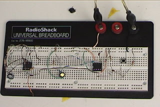
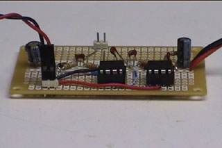
Original scheme edited by Bill Bowden, http://ourworld.compuserve.com/homepages/Bill_Bowden/ 1 555 timer is used as an actual time delay, 3 seconds I believe (can vary depending on need) and the other 555 timer is used as a relay time delay. In other words, when I turn on my cabinet the first timer kicks in it waits 3 seconds and then sends a signal to the other timer to trigger the 12 volt relay to turn on the cabinet. The second timer stays on for milliseconds only long enough to trigger the relay and turn on the TV, it then de-energizes the relay and waits to be triggered again by the cabinet switch. I think you get the general idea, it's nothing more than a glorified rocker switch that you could wire all you components into. The first 2 pictures below were taken from a circuit tester, essentially you build and test your circuit on a solder less board, when your satisfied with the circuit break out the soldering iron...
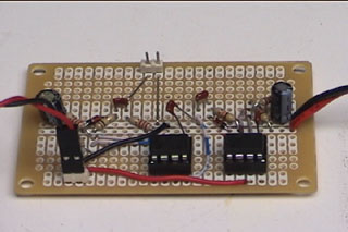
These shots are of the completed circuit.
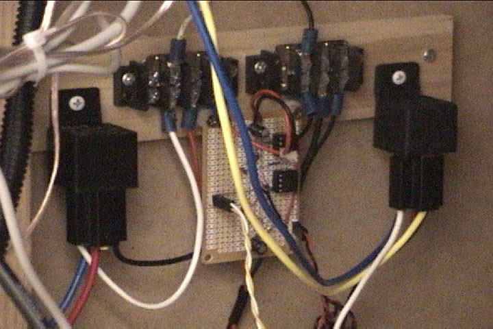
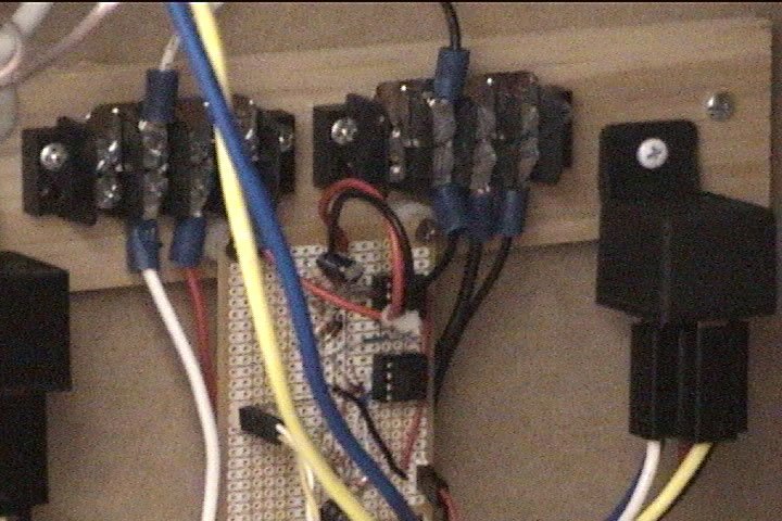
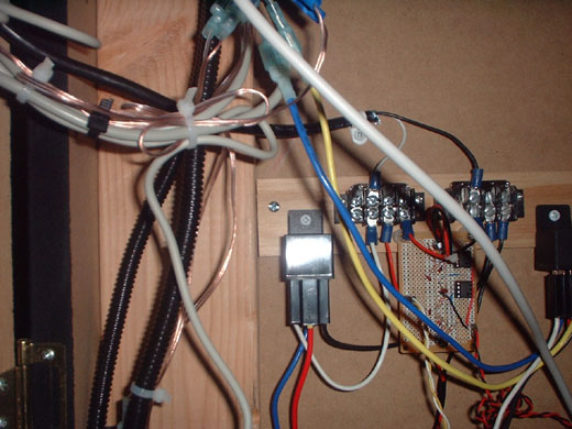
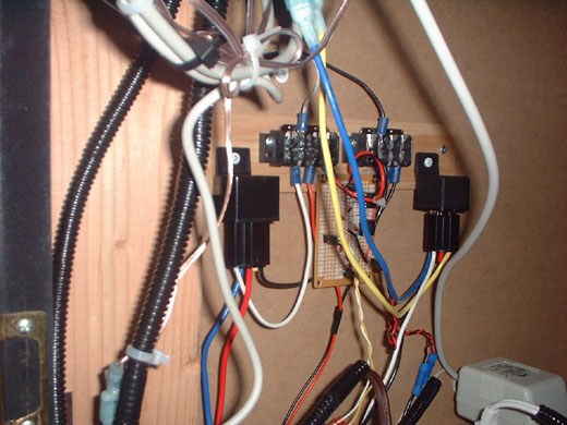
Here is the total setup working and in the cabinet. Notice the 2 relays used.
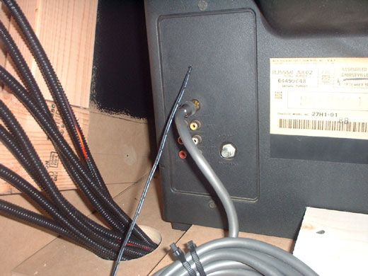
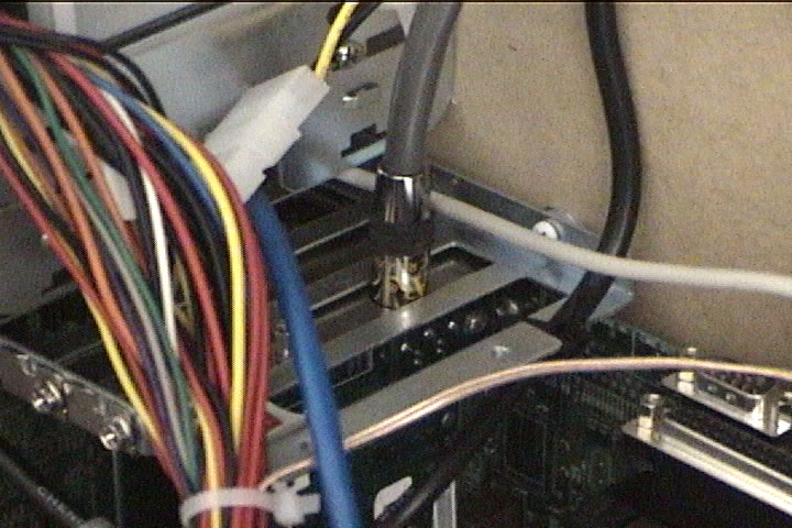
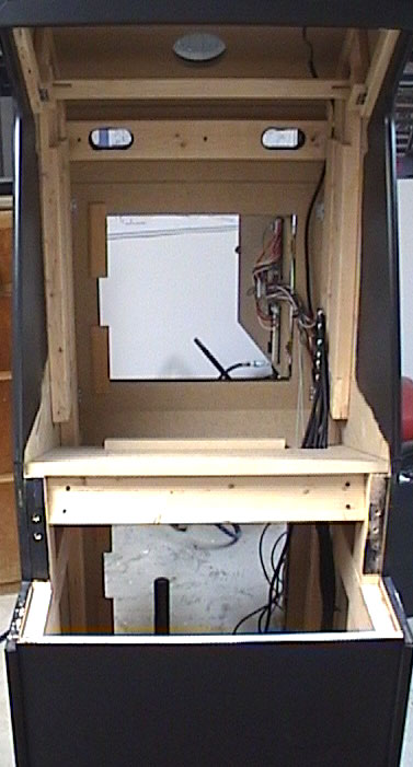
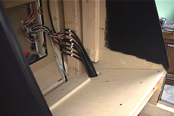
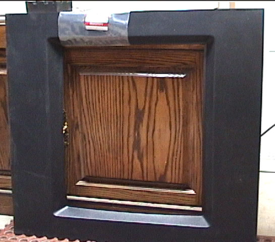
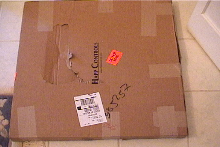
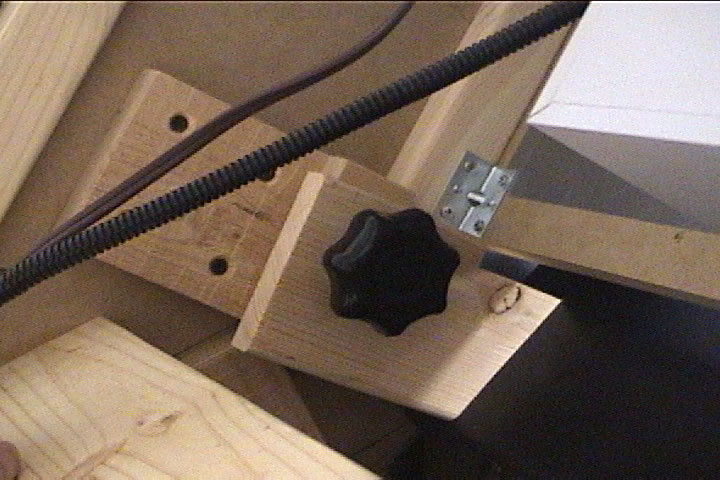
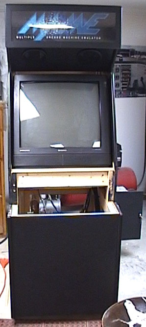
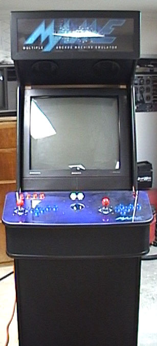
#1 relay is used for shutting the Arcade down from the control panel. It simply responds to the power supply of the PC. When the Arcade is fired up the #1 relay is energized it's contacts are open and it is wired to the TV switch. When you hit the ESC button on the control panel a DOS batch (see the DOS section) file sends a command to the PC to shut down, this in turn cuts the power to the #1 relay and when the contacts close the TV switch closes. #2 relay works in conjunction with the REMOTE Turn/ON as described above. Here are some cabinet pictures of the cabinet shelf and TV setting on the shelf in the cabinet. I used an original monitor bezel for a 27" TV that I ordered from Happ's, I had to do some trimming but it worked out fine (aside from the shipping of the bezel). I also manufactured a hold down clamp for the top of my TV, I didn't want it moving around.
next: the Front End !
|
|
|
Last updated: 05/28/03. |